24 Vdc Wiring Diagram
2320 tm vdc wiring schematic circuit Diagram of 3-phase reversing motor control with 24 vdc control voltage Figure 2-5. 24 vdc circuit wiring schematic.
12v To 3v Converter Circuit | DC To DC Converter - YouTube
Tm vdc wiring schematic Wire diagram(model 667) (24 volt) 12 volt wiring schematic for rv slide out
Figure 2-25. 24 vdc circuit wiring schematic (145 amp) (sheet 1 of 3)
Wiring volt light diagram rv slide schematicPhase motor diagram reversing control vdc voltage 24 and 36-volt wiring diagrams – trollingmotors.netWiring volt 24 24v diagram starter dual bike hayabusa batteries system wire motorcycle starting suzuki question schnitz 12v technical ryan.
24 volt trolling motor battery wiring diagram3v 12v dc converter circuit Trolling 24v 12v mbgforum changing12v to 3v converter circuit.

Diagram wire volt motorguide model
24v wiring question....Vdc conventional constant Circuit diagram of a vdc: (a) the conventional vdc and (b) the proposedWiring trolling volt motor diagram 24v 24 minn kota plug system battery hook electric wire batteries diagrams 12v motors do.
.

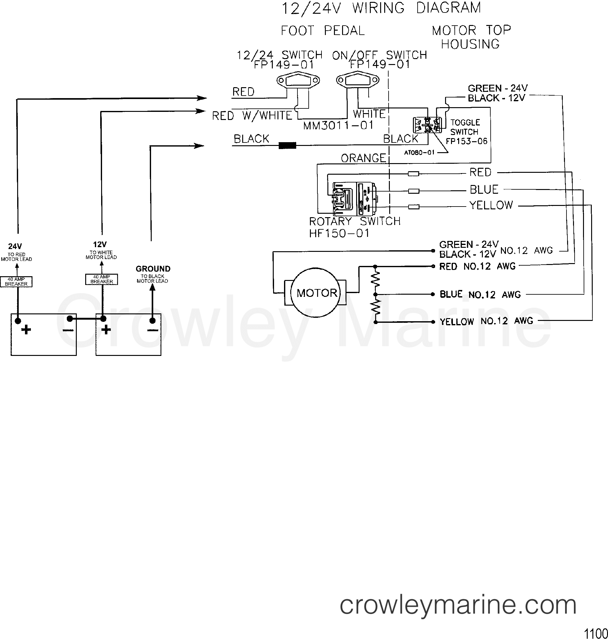
WIRE DIAGRAM(MODEL 667) (24 VOLT) - 1999 Electric Trolling Motor 12/24V

12v To 3v Converter Circuit | DC To DC Converter - YouTube

Figure 2-5. 24 VDC Circuit Wiring Schematic.

24v wiring question.... | General Bike Related Topics | Hayabusa Owners

Diagram of 3-Phase Reversing Motor Control with 24 VDC Control Voltage

Figure 2-25. 24 vdc Circuit Wiring Schematic (145 AMP) (Sheet 1 of 3)

Circuit diagram of a VDC: (a) the conventional VDC and (b) the proposed

12 Volt Wiring Schematic For Rv Slide Out